|
|
|
 |
 |
 |
 |
 |
 |
 |
| Description The Festool Hole Guide is basically a jig system that fits onto the Festool Guide rails. The system is designed to allow the drilling of 32mm system holes which are on 32mm or 16mm spacing. The system uses a router as the drill which makes for very clean and round holes even in materials prone to chip-out such as Melamine. The system is designed to accept Festool brand routers; note that the router and guide are not included with the kit. |
 |
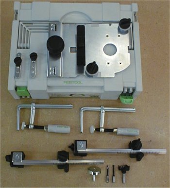 |
The system comes in its own fitted
Systainer. The main element is a guide plate which rides on the Guide Rail, there are also
two positioning devices which set the Guide Rail in the desired position relative to the
workpiece edge, two end stops which are fitted to the underside of the Guide Rail used to
position it relative to the workpiece end, two clamps which can be fitted to the Guide as
well, a centering mandrel to center the router on the guide plate, three router bits, and
a wrench (not shown). All these parts fit into the Systainer just so, there is just a
little room left over for an extra clamp or two or more bits but not much else. This system is also (of course) compatible with the Festool Multi Function Tables (MFT) which allow for more positioning and clamping options than what will be described here. There are two sizes of Guide Rails available with these 32mm holes, one 1080mm (42")long and another 2424mm (95"), the Guide Rails can also be joined together with a special fitting; this would for example allow two 42" Guides (which are more transportable) to become a 2160mm Guide. |
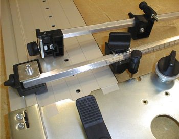
| Alignment Here is a close-up of the guide plate and the two positioning devices. There are two alignments that must be performed on a new system. The first is the standard one required of all Festool accessories that use the Guide Rail; the built-in adjustments on the guide plate must be made to fit the raised beam on the Guide Rail. This is easy to do and is a one-time adjustment. The positioning devices need to be calibrated prior to use. This must be done for both positioning devices, it's easy to do and is also a one-time operation. |
 |
 |
Setup This is a long view of the system setup for use on a workbench. Note that the Guide has the clamps (not visible) installed which have firmly fastened the entire system to the bench. The Guide Rail itself is fairly stable, one could simply place it properly on the workpiece and begin drilling. The problem is that some materials (especially Melamine) will move on the bench during this operation unless clamped. Depending on where the holes need to be drilled, clamps could be installed on the top. Note also that there are two moveable stops shown (not included with the kit) that fit onto the Guide Rail which can be used to limit the number of holes drilled. |
| The positioning devices are shown installed, when drilling these may be in the way, they are easily removed if desired. Just in case it isn't clear, these positioning devices can be placed anywhere along the Guide Rail, they are not tied to any 32mm increment; they are just a reference used to position the Guide Rail from the edge; they DO NOT hold the guide in place. | |
| Here is a closer view of the guide plate with the
router installed. Every time the router is installed onto the guide plate it must be
calibrated to the guide plate. This is accomplished easily enough by installing the
centering mandrel into the router and then placing the router into the guide plate and
tightening the two "top-hat" knobs. This guarantees the router will be installed
centered every time. Note that the drilled holes are some distance away from the guide. This distance is always the same, the distance the center of the holes are from the edge is controlled by the position of the sliding stop on the octagon rod. |
 |
| In Use On the guide plate there is this sort of large teeter-totter paddle, a spring loaded pin on this device is what engages the holes in the Guide Rail. Moving the rig into position is very easy and once you start drilling it is a very fluid and quick operation. One simply pushes one end of the paddle down, moves the rig and it will lock into the next detent position. The guide plate glides smoothly across the rail and locks positively in any 32mm position. Drilling shelf holes is a very simple operation and is pretty anticlimactic once the system has been setup. |
|
 |
The instructions describe a set procedure for orienting the
setup to drill a mating set of holes. Once the first set of holes are drilled either the
Guide Rail OR the workpiece needs to be rotated 180 degrees. Shown in this illustration is
the workpiece being rotated; I think this probably a little easier than rotating the Guide
if clamps are involved but it can be done either way. Installed on the bottom of the Guide
are two stops, these are fastened by and attuned to the 32mm detent holes in the Guide
itself. It isn't too critical where these stops are placed because of the precision of
their 32mm locations. It is critical HOW they are installed however, a reference pin on
either side of theses stop units control either a 32mm or 16mm "from the end"
reference (holes are still 32mm apart though) In the first setup the stop marked A is the reference for the 3-4 edge of the workpiece and holes are drilled along the 2-4 edge. For the next series of holes the stop marked B is the reference for the 3-4 edge of the workpiece and holes are drilled along the 3-1 edge. |
| Depending upon the width of the workpiece one may or
may not be able to see the previously drilled holes during the second setup. Note that (in
this procedure) also a DIFFERENT set of holes in the Guide will be used to drill aligned
holes thus any stops on the Guide will also be misplaced for the second set of holes. In
these situations I would advise placing some kind limit marks either on the guide or the
workpiece to ensure proper alignment. It may or may not be evident at this point that this "standard" (as described in the instructions) method of alignment for drilling holes is not the only method that can be used. On wider pieces especially one may be able to drill the all the holes using the same "A "stop without rotating the workpiece. The use of the MFT also allows a similar procedure to be used instead. I've only described one use of the Hole Guide System, in reality one could probably write a small book on its use and the additional accessories that could be used with it. Summary |
|
In the interest of full disclosure Festool provided this product to facilitate this review.
|
 |
 |
 |
 |
 |
 |
 |