|
|
|
Unisaw Sliding Table Modification
Back-to - Unisaw Sliding Table Modification
|
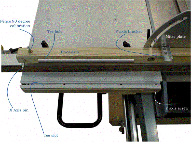
| The fence assembly is shown detached
and laying down on the fence face. The aluminum T-slot embedded in the table surface
can be seen as well as the T-bolts in the bottom of the pivot arm that slide into the
T-slot when the fence assembly is attached to the table. Also visible is the X axis pin in the left end of the pivot arm. The X axis pin is a 1/4-20 bolt with the head removed. The pin will slide into a slot at the left end of the table surface and will make contact with the bracket shown above. The X axis pin and bracket limits the fence travel in one axis. The T-bolts will constrain the fence in the Y axis somewhat but not enough to achieve a calibrated home fence position. To ensure that the fence assembly is returned to its home position, a limit plate (Y axis bracket) contacts a screw head (Y axis screw) embedded in the sliding table. One of the best features of this fence design is that there are no precision parts in the fence calibration system. The X axis pin and the Y axis bracket and the Z surface (sliding table) combined together achieve a repeatable and accurate fence home position.
|
 |