|
|
|
Hammer B3 / K3
Outrigger Attachment Modification
 |
 |
 |
 |
 |
 |
 |
|
I have found that it is beneficial to use B3 without the outrigger table unless I am cross cutting long pieces or sheet goods. Its removable feature is also handy in a small workspace because it reduces the footprint of the machine quite a bit. Although the outrigger is designed to be easily removed and installed, there is a little bit of difficulty in doing so due to the stopped groove in the sliding table interfering with the alignment bolts imbedded in the outrigger. This small inconvenience is not really a big deal but I thought I would be able to improve upon the situation very easily without any detrimental performance or accuracy side effects. The easiest way to relieve the alignment bolt interference would be to mill the slider groove with a router so that it was no longer "stopped" but continued to the end of the slider. I was hesitant to do this because I didn’t want to potentially hurt the resale value or give myself an opportunity to make a mistake on such a visible and expensive part. |
|
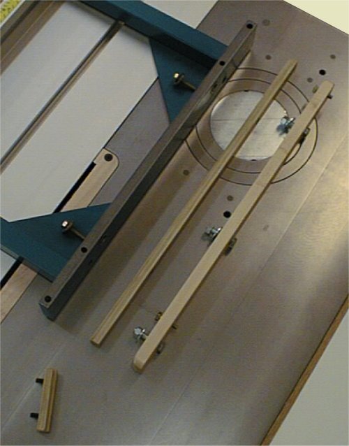 |
The solution was to use bolt-on modifications that did not require any permanent changes to the machine; this became requirement #1. A second requirement was to use simply made parts from commonly available materials. It should be noted that since the outrigger can only be moved a relatively short distance back from the outfeed end of the slider, I did not bother to design the modification to accommodate a slider position other than at the extreme outfeed end. |
| The solution I chose to use involved removing the alignment bolts in the outrigger, this eliminated the interference with the sliding table. To regain the alignment required by the outrigger table, I made a plate that attached to the underside of the sliding table. This plate uses two jack screws to perform the same alignment task previously performed by the bolts in the outrigger table. | 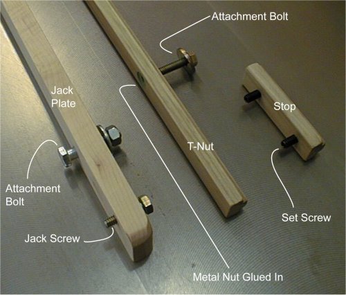 |
| Another aspect of the modification was to replace the two separate flat nuts used to bolt-up the outrigger to the sliding table. The replacement for the flat nuts is a wooden T-nut with embedded steel nuts epoxied in. This totally eliminates the minor inconvenience caused when these flat nuts are turned the wrong way when attempting to re-install the system. As a side effect of making the stock for the wooden T-nut, I made a shorter version that has threaded holes for two set-screws. This stop makes it easy to put the outrigger on exactly the same every time. This stop is optional and was replaced by a modification made at a later date. | |
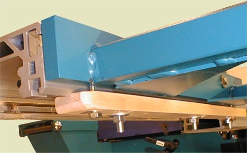 |
This end view shows the outrigger attached. The jack plate sets the height of the outrigger to the exact height needed very easily. The jack plate does not extend to the end of the slider due to the small um-milled profile at the end of the slider. The bolts used to attach the jack plate are common 5/16-18 hex head types. I used 1/4-20 bolts to attach the outrigger instead of the metric plastic handled bolts that came with the Hammer just because I prefer them. |
| The view below shows the end view of the sliding table and outrigger using the new attachment blocks. The outrigger is shown in red, the attachment and jack bolts are green, and the T-nut and jack plate are the hatched blue areas. |
 |
 |
 |
 |
 |
 |
 |
 |