|
|
|
Hammer B3 Jigs & Modifications
 |
 |
 |
 |
 |
 |
 |
The following are some of the minor modifications I have made to the Hammer B3 Combination machine.
|
| This is a "bumper" I made
for the outrigger table. Sometimes with the outrigger attached sheetgoods can droop
down during a rip cut or just when moving them on the saw. This would sometimes
result in an edge catching on the outrigger parts. To try and solve some of that I moved the large aluminum T-track towards the outfeed side and bolted a 1" thick piece of Maple with rounded edges to the front of the outrigger table. This Maple strip really sets off the machine and makes it prettier too! |
 |
 |
The calibration provided for
setting the crosscut fence to 90 degrees leaves a little to be desired in the way of
accuracy and convenience. To overcome that I decided to install this bolt / rotating
stop at the end of the outrigger table. It a very simple modification. Basically I removed the plastic end-cap and installed a maple block which has a hole threaded for a 1/4-20 hex bolt. The hole perpendicular to the bolt is for a #10 setscrew which locks the bolt in place once the calibration is set. The fence can be positioned for 90 degrees very easily and precisely with this set-up. |
| A good crosscut fence with
reliable, easy to use flip-stop is as important a feature on a sliding table as a quality
rip fence. I have a long crosscut fence which I leave attached to the outrigger
table but I needed a good fence to use when the table is detached and for normal stock
sizes; seen here is the result. I used the miter gauge assembly to clamp the fence to the slider however I took the Hammer 90 degree stop off. I replaced it with a stop on the standard support table. This gives me a little better resolution in setting the fence for 90 degrees. |
 |
| I made a couple of
fence stops as well. I had intended to make ones a little fancier that these but I
opted for an easier to produce design. The stop blocks are made of Maple and
Vee-grooved on the bottom to mate matching profiles in the fence. The stops
themselves are small pieces of T-track. A T-track is embedded in the fence to accept
the 1/4-20 bolt in the stop block. I applied a tape and made an adjustable cursor
for the stops too. I will probably build a couple of better looking fences out of hardwood later but for now this one will do. |
|
 |
It isn't apparent in these
pages but many of the modifications I have made to my machine have an impact far beyond
their specific application. The tilting power feeder bracket is a good example of
this. Because I wanted to get the tilting feeder bracket out of the way so it would not mar stock, I lowered the whole bracket. Lowering the bracket prevented the use of the Hammer rip fence rail on the outfeed side of the table. Because there was no rail, I couldn't use the Hammer outfeed table assessories. |
| This eventually led to
the outfeed table design seen here. I have three such tables, the one shown is sized
so that the feeder can still be used. I have another that is wider and covers the
feeder when stowed, this is the table I leave on the machine. The last table is one
of the same width as shown but about 40" long to handle longer rips. The tables clamp to a wooden bar attached to the saw table and is supported by a bracket attached to the saw. None of the effort involved in making these tables is really worth it unless driven by a change such as the one mentioned. If possible, the Hammer tables would be the preferred choice. |
|
 |
This view shows the new rip fence installation on the B3. I replaced the B3L type that I had previously modified with this new unit. For the most part the installation was pretty easy, I did have to remove about 1/8" of material from the aluminum casting but other than that there was not much else done in order to get it to fit. |
 |
This is a very simple angle hold-down device. Although there is a separate clamp that can be purchased to fit onto the sliding table, I did not particularly like how it looked or its' ergonomic design. In using the sliding table for crosscuts, it becomes obvious that a clamp of some sort would be beneficial, this device serves that need at least 80% of the time. |
| This
is another view of the clamp, there is a tenon (or key) that runs in the T-slot in the
sliding table (loose fit). Under the tenon is a piece of bar-stock threaded to
accept a 1/4-20 screw in two places. One screw is used to hold the bar stock in
rough alignment with the tenon and allow it some slack. The other is used to tighten
the device down to the sliding table. So far this simple device has worked very well, it is easy and quick to remove and install and holds down the edge of the work piece good enough that usually no other pressure is needed. |
 |
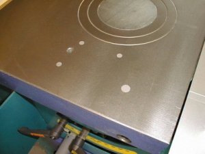 |
One thing that has bothered
me more than it should are the several holes in the iron top. The holes aren't
required to be through-type holes so I filled them with gray epoxy and sanded them flush
with the surface. In this photo, the flash makes the epoxy show up more than they
appear in normal lighting. This modification doesn't make the machine work any better but at least I'm not constantly reminded of them anymore. In case you are wondering, I put some soft material in the bottom of the holes in case there were any need to move the bolts they are associated with. Also, I could reverse the process if I chose to later. |
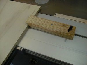
| This is a very simple modification to the crosscut fence. To keep long thin material from bowing, I cut and profiled a 1.5" aluminum angle and screwed it to the bottom of the fence extension. This is not really useful with the outrigger since it is close enough to the end of the fence for support anyway. It is useful when the fence extension is drawn extended out or if the crosscut fence were used without the outrigger table. |  |
 |
This is a picture of the offcut ramp jig. As detailed in the review, due to the air stream around the blade and the throat plate opening and bevel, small offcuts can be launched by the blade. This is bad enough if you are just squaring the end of a board but if you actually need to use the offcut, it is quite unacceptable. |
| Aigner makes a
simple jig that directs the offcut out away from the influence of the blade so that they
cannot be caught. This is a copy of the Aigner jig, I made it out of scrap in just a
few minutes. The ramp is held in place by two magnets on the bottom (see inset), because of the magnets, it can be stored for ready use anywhere on the machine.
|
|
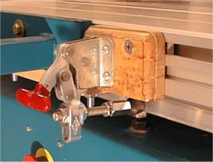
| This is a Carr-Lane clamp I used on a previous version of the Delta sliding table modification. Unlike other toggle clamps, this one can automatically adapt itself to different size material; it can also be adjusted for clamping force. With about 1/4" of free space under the pad (as shown) the self adjusting feature of the clamp would allow it to apply clamping forces to stock from 1/2" to 1" thick very easily or even thicker materials with more effort. | 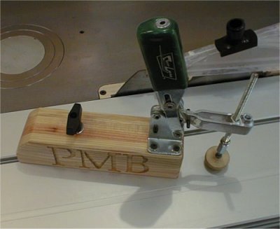 |
| In order to use this
type of clamp it needed to be elevated quite a bit from the sliding table. The base
for the clamp is about 10" long, the width of the base is 2 3/4" and the height
is 2 1/4". The clamp has been modified to use either a 5/16"-18 or
3/8"-16 bolt or clamp pad. 5/16-18 and 3/8-16 threaded couplings are welded
into the clamp bar so that I could use a threaded rod and a new swivel clamp pad designed
afterwards. In this version, this clamp can swivel around to clamp at any point across the width of the sliding table.
|
|
 |
The outrigger can be easily removed
from the B3 but then it must be stowed some place out of the way; this modification is
designed to provide a place to store it. After living with this modification for a while I've found it to be in the way somewhat. I need to find another place to put this. I bolted two small hardwood boards to hang the outrigger frame onto. They are assembled with a couple of washers underneath the left side to tilt them upwards to reduce the chance that the outrigger could vibrate or be nudged off. |
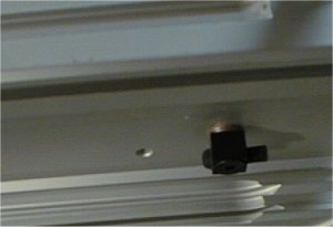
| This is a picture of the underside
of the sliding table. The black square looking thing with a dowel out the back is
the bumper used to keep the sliding table from being slid too far forward or back; there
are two of these on the slider. This bumper contacts the head of an Allen bolt in
the sliding table guide. To make the bumper operate better, I lowered it by the thickness of a couple of washers and applied a small black rubber pad to the contact area. Now when it hits the stop it isn't so jarring. |
 |
 |
This toggle clamp serves two functions. It creates a stop for the outrigger (not very important) and it prevents movement of the sliding table when desired. The Hammer comes with a stop mechanism to keep the slider from moving but it will only operate in one position. I have found that there are two stop positions desirable on a slider. The first is basically a "stowed" position so it doesn't get moved inadvertently and the second is a "loading" position; this is used when loading large sheetgoods onto the slider before ready for the cut. Since the saw could be on during this process, it is desirable to prevent movement into the blade until ready. |
| The toggle clamp is mounted to a wooden block secured to the slider with a big square nut. Due to the length of the bolt, there is some movement in the slider and it could be overpowered if enough force were applied. This stop can be used over a span of several feet instead of just a single position. | |
| The tilting feeder bracket when
installed is only about 1/8" below the surface of the iron table with the feeder
folded out of the way in its "stowed" position. I anticipated defacing
some expensive veneer plywood with the exposed sharp edges of the bracket so I decided to
lower the bracket by as much as possible. This will also provide needed room for a
modification to be described later. To locate the bracket in its new position I drilled new holes in the cabinet and the bracket itself. It was necessary to drill new bracket holes due to an interior horizontal brace inside the cabinet. |
 |
 |
With the feeder bracket in its new position, it is about 2 inches lower than the plane of the iron table. Although this modification appears like a lot of work, it didn't take all that long to perform. The stock feeder I use is a small 1/4hp unit which still has plenty of clearance between it an the floor when folded, larger feeders may not have enough room since their columns are typically taller. |
 |
 |
 |
 |
 |
 |
 |