|
|
|
Extension Table for the Hammer B3 / K3
 |
 |
 |
 |
 |
 |
 |
| The OEM extension table for the Hammer B3 or K3 is a series of formed steel wings that are attached using the fore and aft rip fence rails. I've noted some issues with the sub-optimal design of the rip fence itself and the alignment issues inherent in the design of the OEM tables elsewhere. Having replaced the original rip fence with something far superior I also wanted a replacement for the extension table. |  |
| The steel wings themselves are acceptable as a
table, the issues is in how they are mounted in the original design. I could have
incorporated the steel wings into this table design but it would have made mounting the
router a bit tougher. There were a few goals that I had in mind when I was designing this extension table:
As you can see, the table was just part of a larger project. Early in the design I decided that I wanted the router insert as close as possible to the saw cabinet. My B3 is normally parked with the right side up against a wall and I wanted to operate the router basically from the same stance one would operate the saw (relative to infeed direction). I also wanted to mount the top to the cabinet in such a way that it could be easily aligned with the main was table. I also wanted to incorporate dust collection for the router with the 4" saw hookup for the sake of convenience. |
 |
With the top removed, you can see that
the router cabinet is not nearly as deep as the saw cabinet. The cabinet is
basically a plenum for the dust collector on the router side and a drawer unit on its
right side. The plenum has a door on the front for router access with a blast gate
in the bottom and ramps to direct the chip flow through the blast gate. There is a 4" Tee section from the saw collection point exiting the saw cabinet (modified from the OEM pickup location). I've installed a blase gate at the exit point on the saw with a long extension. On the picture at the top you can see a large white knob just above the tire. This is that extension. |
| The 4" PVC duct continues to a Tee under the router chamber. The reason for using a Tee here is that it's end can be uncapped and a DC hose hooked between it and a router fence port for both above and below chip collection. | |
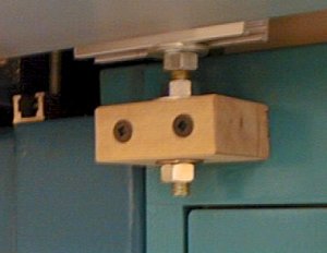
| The table is attached primarily
through the use of four 5/16" studs which are received by blocks attached to the
router cabinet. The studs are attached to the top using small sections of T-track. Basically I wanted to ensure that there was some ability to adjust the table X and Y so the locations of the studs or their mating holes would not have to be perfect. The table is adjusted in the Z axis (height) using jam nuts on the studs. The table also has four 1/4-20 bolts to attach it to the saw cabinet itself. These are not so much attachment points as they are levelers. Tier main purpose is to ensure that the joint between the iron table and the extension is flat. This is important because the rip fence would catch on an edge and it can also affect router operations. |
 |
 |
The top is 3/4" Melamine with a
web frame underneath. Near the router insert it is reinforced with an additional
1/2" plywood section. The Melamine is covered with a piece of laminate on the
top surface. The reason for using Melamine is because it is very stable and flat. A key design element is to make sure that the table is weaker than the object it is attached to. This is to ensure that the table will be the item that can be deformed into alignment. Otherwise if the table were the strongest element, IT would control alignment. |
| Whenever possible I try and use the
dead space under machines to store items related to the use of that machine. This is
one of the drawers in the router cabinet related to the Bosch 1617 router
and the Woodpecker Precision Router Lift (PRL)that I use in this
table. I don't store the Hammer tools in this unit because I have a special wall
mounted board to hold them that I prefer over a drawer. Not seen in any of these views is the remote switch attached to the rip fence rail to turn the router on or off and the Incra LS Super System that I use as a router fence. |
 |
Return to the Hammer B3 Index Page
 |
 |
 |
 |
 |
 |
 |